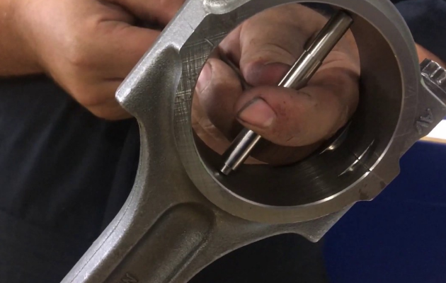
Knowing how to check connecting rod alignment is an essential skill for engine builders, mechanics, and automotive enthusiasts. Properly aligned connecting rods ensure optimal engine performance and longevity, while misaligned connecting rods can lead to uneven wear, reduced power, and even catastrophic engine failure. In this article, we will discuss the importance of connecting rod alignment and provide a step-by-step guide to checking the alignment of your connecting rods.
The Importance of Connecting Rod Alignment Connecting rods play a critical role in internal combustion engines by transferring the linear motion of the piston to the rotational motion of the crankshaft. A misaligned connecting rod can cause increased friction, premature wear on bearings, and decreased power output. Regularly checking and maintaining proper connecting rod alignment is crucial to keeping your engine running smoothly and efficiently.
Tools Needed to Check Connecting Rod Alignment Before you begin, you’ll need a few essential tools and equipment:
- Flat work surface: A flat, level, and clean work surface, such as a granite or cast iron surface plate, is necessary for accurate measurements.
- Dial indicator: A dial indicator with a magnetic base or a dial bore gauge is required for precise measurements.
- V-blocks: V-blocks are used to support the connecting rod while measuring.
- Micrometer or calipers: A micrometer or calipers will be needed to measure the connecting rod’s dimensions.
Step-by-Step Guide to Checking Connecting Rod Alignment
- Clean and Inspect the Connecting Rod: Begin by thoroughly cleaning the connecting rod to remove any dirt, oil, or debris. Visually inspect the connecting rod for any obvious signs of damage, such as cracks or excessive wear.
- Measure the Big End Bore: Using a micrometer or calipers, measure the diameter of the connecting rod’s big end bore. Record the measurement, as it will be used to determine the alignment later in the process.

- Set Up the Dial Indicator: Mount the dial indicator on a magnetic base, and position the indicator’s plunger on the centerline of the connecting rod’s small end. Ensure that the plunger is parallel to the connecting rod and has sufficient travel for measurement.
- Take Measurements: With the dial indicator set to zero, slowly rotate the connecting rod around its axis, taking note of the maximum and minimum dial indicator readings. The difference between the maximum and minimum readings is the amount of misalignment in the connecting rod. Compare your findings to the manufacturer’s specifications to determine if the connecting rod is within acceptable tolerances.
- Check for Twist: To check for twist in the connecting rod, place the connecting rod on the V-blocks with the big end facing upward. Position the dial indicator’s plunger on the edge of the big end bore, and rotate the connecting rod around its axis. Record the maximum and minimum dial indicator readings, and compare them to the manufacturer’s specifications to determine if the connecting rod has a twist.
By following these steps, you can effectively check your connecting rods for alignment and address any issues before they cause damage to your engine. Remember, regularly inspecting and maintaining your engine components is key to ensuring optimal engine performance and reliability.
